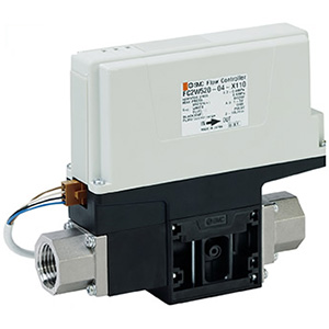
FC2W-X110
FC2W504 03 X110
How to Order
Piping port size
Symbol Port size
03
3/8
Piping port size
Symbol Port size
04
1/2
Lead wire
3
Lead wire with connector (3 m)
Flow rate control range
0.5 to 4.0 L/min
2.0 to 16.0 L/min
FC2W520 X110
Specifications
Input Signal — Flow Rate Characteristics
Output Signal Pulse Frequency — Flow Rate Characteristics
Model
FC2W504-03-3-X110 FC2W520-04-3-X110
Applicable fluid
Water
Flow rate detection method
Karman vortex
Flow rate control range
0.5 to 4.0 L/min 2.0 to 16.0 L/min
Flow rate measurement range
0.4 to 4.2 L/min 1.6 to 16.8 L/min
Operating pressure range
0.2 to 0.4 MPa (Fluid temperature: 0 to 50°C)
Withstand pressure
0.6 MPa
Operating temperature range/Fluid temperature range
0 to 50°C (No condensation)
Control accuracy
±5%F.S.
Temperature characteristics
±5%F.S. (0 to 50°C, 25°C reference)
Leakage when fully closed
*
1
0.4 L/min or less 1 L/min or less
Fully close function
Shutoff function not provided
Response time
*
2
10 s or less
Input signal
*
3
Analog voltage input: 1 to 5 VDC Input impedance: 1 MΩ
Output signal
*
3
Flow rate pulse output
LED indicator
When the power is ON (PWR: Green is ON) When an error is detected (ERR: Red is ON or flashing.)
*
4
Power supply voltage
24 VDC±10%
Current consumption
0.5 A
Main materials of parts in contact with fluid
PPS, PP, POM, FKM, Stainless steel 303, Stainless steel 304, SCS13 Non-grease specifications
Piping port size
03: Rc3/8 04: Rc1/2
Weight
515 g 530 g
*1
Use an external shutoff valve to stop the flow in an emergency.
Recommended 2 port solenoid valves
Series
Recommended 2 port
solenoid valves
Note
FC2W504
VXZ232D
N.C./Stainless steel/
Port size Rc3/8
FC2W520
VXZ242G
N.C./Stainless steel/
Port size Rc1/2
*2
Time taken until the flow rate reaches approximately 90% of the
set value relative to the flow rate command value (input signal).
*3
Refer to Graphs 1 and 2 for the relationship between the flow
rate and the I/O signals.
*4
The LED status when an error is detected is summarized in the
table below.
LED Status When an Error is Detected
Wiring Diagrams
Example of output signal wiring
FC2W504
(Graph 1)
Status LED status Action to be taken
EEPROM error
Stays lit.
Automatically recovered when reading
and writing are performed correctly.
Over
current
Flashing: Flashing cycle of 500 ms
Not automatically recovered.
Turn power off and then on
again.
Insufficient
supply flow
rate
Flashing: Two flashing cycles of 250 ms at two-second intervals
Error automatically resets
when the supply flow rate is
recovered (LED goes off).
FC2W504
FC2W520
(Graph 2)
FC2W520
3
304
1
A