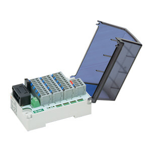
4-branch
input
4-branch
output
Communication
connector
Power supply
connector
EX510-GMJ1 EX510-GDN1 EX510-GPR1
Model
®
Cover view
16
PWR
(V)
PWR
BUS
OUTPUT
INPUT
70 ± 0.2 5
40
80
54 ± 0.2
64
5
25.7
60
COM A
COM B
COM C
COM D
OUTPUTINPUT
2 x M4
Mounting hole
How to Order
CC-Link
DeviceNet
PROFIBUS DP
MJ1
DN1
PR1
Communication protocol
MJ1
EX510-G
Dimensions
GW Unit
Specifications
Note 1) Please note that the version is subject to change.
Note 2) Each file can be downloaded from SMC’s website
(http://www.smcworld.com/).
Note 3) For detailed specifications other than the above, re-
fer to the separate technical operation manual that
can be downloaded from SMC’s website
(http://www.smcworld.com/).
Specified file
Note 2)
Terminal resistor
For unit
For sensors
For valve
Number of inputs
Connection input device
Supply voltage
Supply current
Number of outputs
Supply voltage
Supply current
Enclosure
Operating temperature range
Operating humidity range
Withstand voltage
Insulation resistance
Vibration resistance
Impact resistance
CC-Link
Ver. 1.10
—
24 VDC±20%
11 to 25 VDC
(Supplied by DeviceNet
circuit, 50 mA or less)
156 k/625 k/
2.5 M/5 M/10 Mbps
125 k/250 k/
500 kbps
24 VDC±20%
24 VDC±20%
9.6 k/19.2 k/45.45 k/
93.75 k/187.5 k/500 k/
1.5 M/3 M/6 M/12 Mbps
Not applicable
Communication connector 1 pc.,
Power suppy connector 2 pcs.
Communication connector 1 pc.,
Power suppy connector 2 pcs.,
Terminal resistor 1 pc.
Applicable
96/96
(3 stations, remote device station)
∗ Possible to change depending
on the switch setting
64/64
∗ Possible to change depending on
the switch setting
DeviceNet
Release 2.0
EDS file
24 VDC±10%/–5%
100 mA or less (single GW unit)
64 points (16 points x 4 branches) ∗ Possible to change depending on the switch setting
The EX510 series input unit (connection from communication port A to D)
24 VDC
Max. 4A (Max. 1 A per branch)
64 points (16 points x 4 branches) ∗ Possible to change depending on the switch setting
24 VDC
Max. 6 A (Max. 1.5 A per branch)
20 m or less
IP20
–10 to 50°C
35 to 85%RH (with no condensation)
500 VAC for 1 min. between external terminals and FG
10 MΩ or more (500 VDC) between external terminals and FG
10 to 150 Hz with a 0.035 mm amplitude or 4.9 m/s
2
in each X, Y, Z direction for 2 hrs (De-energized)
147 m/s
2
in each X, Y, Z direction, 3 times (De-energized)
CE marking, UL (CSA)
PROFIBUS DP
DP-V0
GSD file
Protocol
Version
Note 1)
Applicable
system
Occupied area (Number
of inputs/outputs)
The EX510 series SI unit manifold and output unit
(connection from communication port A to D)
Communication
specification
Power
supply
Internal current consumption
Standard
Accessory
Branch cable length
Output
specification
Input
specification
Environmental
resistance
Communication
speed
Connection output
device
1702
Series EX510
Decentralized Serial Wiring
(GW System, 4 Branches)