Specifications
Bore size (mm)
Fluid
Action
Operating pressure range
Proof pressure
Ambient and fluid temperature
Cushion
Lubrication
Stroke length tolerance
Front/Side port
Bottom port
1610 20 25 32 40 50 63 80 100
Air
Double acting
0.1 to 0.8 MPa
1.2 MPa
5 to 60°C
Air cushion
Non-lube
M5 x 0.8
ø5
Rc 3/8
ø11ø10 ø16 ø18
Shock Absorber Specifications Piston Speed
Bore size (mm)
Without stroke adjusting unit
10
100 to 500 mm/s
100 to 200 mm/s
100 to 1000 mm/s
16 to 100
100 to 1000 mm/s
100 to 1000 mm/s
(1)
100 to 1500 mm/s
(2)
A unit
L unit and H unit
Stroke
adjusting unit
Model
Max. energy absorption (J)
Stroke absorption (mm)
Max. collision speed (mm/s)
Max. operating frequency(cycle/min)
Extended
Retracted
RB
0805
1.0
5
1000
80
1.96
3.83
RB
2015
58.8
15
1500
25
8.34
20.50
RB
0806
2.9
6
1500
80
1.96
4.22
RB
1007
5.9
7
1500
70
4.22
6.86
RB
1412
19.6
12
1500
45
6.86
15.98
Standard Stroke
Bore size
(mm)
10, 16
20, 25, 32, 40
50, 63, 80, 100
Standard stroke (mm)
∗
100, 200, 300, 400, 500, 600, 700
800, 900, 1000, 1200, 1400, 1600
1800, 2000
3000
5000
Maximum manufacturable stroke
(mm)
JIS Symbol
0.2 to 0.8MPa
Rubber bumper
ø4
ø6
5 to 60
Stroke Adjusting Unit Specifications
Bore size (mm)
Configuration
Shock absorber model
Unit symbol
Fine stroke adjustment range (mm)
Stroke adjustment range
16
A
With
adjusting
bolt
With
adjusting
bolt
With
adjusting
bolt
With
adjusting
bolt
With
adjusting
bolt
With
adjusting
bolt
AH
10 20
L
AH
RB
0805
+
with
adjusting
bolt
RB
0806
+
with
adjusting
bolt
RB
1007
+
with
adjusting
bolt
RB
1007
+
with
adjusting
bolt
RB
1412
+
with
adjusting
bolt
RB
1412
+
with
adjusting
bolt
RB
1412
+
with
adjusting
bolt
RB
2015
+
with
adjusting
bolt
RB
2015
+
with
adjusting
bolt
25
L
AH
32
L
AH
40
L
AH
When exceeding the stroke fine adjustment range: Utilize a made-to-order specifications “-X416” and “-X417”.
0 to
–
5.6
0 to –5 0 to –6 0 to –11.5 0 to –12
0 to –16
∗ Stroke adjustment range is applicable for one side when mounted on a cylinder.
—XB11
—XC67
—X168
—X416
—X417
Long stroke type
NBR rubber lining in dust seal band
Helical insert thread specifications
Holder mounting bracket Ι
Holder mounting bracket ΙΙ
Symbol
Specifications
Piping
Port size
1000 or less
1001 to 3000
+1.8
0
+2.8
0
2700 or less , 2701 to 5000
+1.8
0
+2.8
0
Rc 1/8 Rc 1/4
ø8
Rc 1/2
Spring
force (N)
Operating temperature range (°C)
Note 1) Be aware that when the stroke adjusting range is increased by
manipulating the adjusting bolt, the air cushion capacity
decreases. Also, when exceeding the air cushion stroke ranges
on page 960, the piston speed should be 100 to 200 mm per
second.
Note 2) The piston speed is 100 to 1000 mm/s for centralized piping.
Note 3) Use at a speed within the absorption capacity range. Refer to
page 959.
Made to Order Specifications
(
For details, refer to pages 1395 to 1565.
)
∗ Strokes are manufacturable in 1 mm increments, up to the maximum stroke. However, when
exceeding a 2000 mm stroke, specify “-XB11” at the end of the model number.
The shock absorber service life is different from that of the MY1B cylinder depending
on operating conditions. Refer to the RB Series Specific Product Precautions for the
replacement period.
957
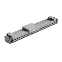
Series MY1B
Mechanically Jointed Rodless Cylinder
Basic Type