Symbol
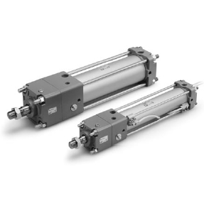
Double acting,
Single rod
Specifications
—XA쏔
—XC3
—XC4
—XC11
—XC14
—XC15
—XC35
Change of rod end shape
Special port location
With heavy duty scraper
Dual stroke cylinder/Single rod
Change of trunnion bracket mounting position
Change of tie-rod length
With coil scraper
Symbol
Specifications
Caution
1. Each switch and mounting style of
cylinder has a different minimum
mountable stroke. Be especially careful
of the center trunnion style.
(Refer to pages 25 and 26 for details.)
Minimum mountable stroke for a
cylinder with auto switch(es)
40 50 63 80 100
Locking action
Unlocking pressure
Lock starting pressure
Max. operating pressure
Locking direction
Holding force (N)
Spring locking (Exhaust locking)
36 psi or more
29 psi or less
145 psi
Both directions
Lock type
Spring locking
Piston speed (mm/s)
100
±0.3
300
±0.6
500
±1.0
1000
±2.0
Condition: Lateral, Supply pressure P = 73 psi
Load weight ······ Upper limit of allowed value
Solenoid valve for locking mounted on the unlocking port
Maximum value of stopping position dispersion from 100 measurements
(mm)
882 1370 2160 3430 5390
∗ Load limits exist depending on the piston speed when locked, mounting direction and
operating pressure.
∗ Be sure to select cylinders in accordance with the procedures on page 1.
Bore size (mm)
40
50, 63
80, 100
Standard stroke (mm)
Note 1)
Long stroke (mm)
Note 2)
25, 50, 75, 100, 125, 150, 175, 200, 250,
300, 350, 400, 450, 500
1200
ø80: 1400
ø100: 1500
800
25, 50, 75, 100, 125, 150, 175, 200, 250,
300, 350, 400, 450, 500, 600
25, 50, 75, 100, 125, 150, 175, 200, 250,
300, 350, 400, 450, 500, 600, 700
Lubrication
Action
Proof pressure
Max. operating pressure
Min. operating pressure
Piston speed
Cushion
Stroke length tolerance
Not required (Non-lube)
Double acting
218 psi
145 psi
12 psi
50 to 1000 mm/s
∗
Air cushion
Without auto switch: 15 to 160°F (No freezing)
With auto switch: 15 to 140°F (No freezing)
Basic, Axial foot, Rod flange, Head flange,
Single clevis, Double clevis, Center trunnion
40 50 63 80 100
Refer to pages 23 to 28 for cylinders with
auto switches.
• Minimum stroke for auto switch mounting
• Auto switch proper mounting position
(detection at stroke end) and mounting height
• Operating range
• Auto switch mounting bracket/Part no.
Bore size (mm)
Note 1) Intermediate strokes other than the above are produced upon receipt of order.
Spacers are not used for intermediate strokes.
Note 2) Long stroke applies to the axial foot and the rod flange.
When exceeding the stroke range for each bracket, determine the maximum stroke
referring to the Selection Table (front matter 29 in Best Pneumatics No. 2).
Up to 250: , 251 to 1000: , 1001 to 1500:
+1.0
0
+1.4
0
+1.8
0
Lock Specifications
Standard Stroke
For cases with auto switches, refer to the table of minimum stroke for
auto switch mounting on pages 25 and 26.
Stopping Accuracy
Bore size (mm)
Ambient and
fluid temperature
Mounting
Made to Order
(For details, refer to Best Pneumatics
No. 3.)
4
Series CNA2
Cylinder with Lock
Double Acting, Single Rod