For M12 For 7/8 inch
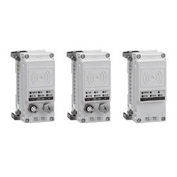
Wireless System
EX600-W Series
How to Order
End plate
End plate mounting position: U side
E U 1EX600 2
Mounting method
Symbol
Description
Nil
Without DIN rail mounting bracket
2
With DIN rail mounting bracket
∗ When the end plate (D side) is
used, the symbol for the
mounting method must be the
same as the U side.
Specifications
Symbol
Specifications
1
Waterproof cover
End Plate (U side)
AXEX600
Analog input
Number of input channels and Connector
Symbol
Number of input channels
Connector
A
2 channels M12 connector (5 pins) 2 pcs.
A
Analog Input Unit
AYEX600
Analog output
Number of output channels and Connector
AMEX600
Analog input/output
Number of input/output channels and Connector
Symbol
Number of input channels Number of output channels
Connector
B
2 channels 2 channels
M12 connector (5 pins)
4 pcs.
Symbol
Number of output channels
Connector
A
2 channels M12 connector (5 pins) 2 pcs.
A
B
Analog Output Unit
Analog Input/Output Unit
∗ For specifications, refer to the Fieldbus
system EX600 series in the Web
Catalog.
∗ For specifications, refer to the Fieldbus
system EX600 series in the Web
Catalog.
∗ For specifications, refer to the Fieldbus
system EX600 series in the Web
Catalog.
∗1 The pin layout for “4” and “5” pin connector
is different.
Refer to the dimensions on page 14.
End plate
End plate mounting position: D side
E DEX600 2 2
Power supply connector
Symbol
Power supply connector
Specifications
2
M12 (5 pins) B-coded IN
3
7/8 inch (5 pins) IN
4
M12 (4/5 pins) A-coded
∗
1
IN/OUT
5
M12 (4/5 pins) A-coded
∗
1
IN/OUT
Mounting method
Symbol
Description Note
Nil
Without DIN rail mounting bracket
—
2
With DIN rail mounting bracket
For SV, S0700, VQC series
3
With DIN rail mounting bracket
For SY series
∗ When the end plate (U side) is used, the symbol for the
mounting method must be the same as the D side.
End Plate (D side)
8