How to Order
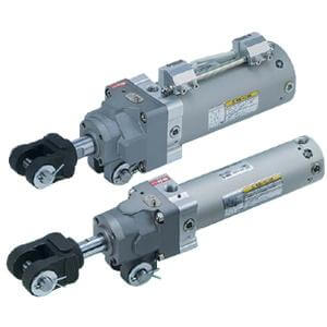
Clamp Cylinder with Lock with Magnetic
Field Resistant Auto Switch
Rod Mounting
ø40, ø50, ø63
Series CLK2G/CLK2P
CLK2G
50
Built-in standard
magnet type
with magnetic field
resistant auto switch
Clevis width
40
50
63
40 mm
50 mm
63 mm
Bore size
Cylinder stroke
50, 75, 100, 125, 150
A Y
100
P4DWSC
CLK2P
50
Built-in strong
magnet type
with magnetic field
resistant auto switch
A Y
B
B
100
P79WSE
None
End bracket
I
IA
Y
YA
Nil
Single knuckle joint (M6 without tap)
Single knuckle joint (M6 with tap)
Double knuckle joint (M6 without tap)
Double knuckle joint (M6 with tap)
Note) Pin (for knuckle), cotter pin and flat
washer are provided as a standard for Y
and YA.
Nil
B
D
L
K
Note 2)
Option
None
Limit switch mounting base
Dog fitting
Note 1)
Foot
Pedestal (for 75, 100, 150 strokes only)
Note 1) When the dog bracket is selected, choose the
rod end bracket IA or YA (M6 with tap).
Note 2) Clevis width B is not available with mounting
base K.
Note 1) PLC: Programmable Logic Controller
Note 2) Refer to page 17 when ordering the auto switch mounting bracket assembly or switch mounting rod assembly.
P4DWSC
P4DWSE
P4DWL
P4DWZ
P79WSE
P74L
P74Z
Type
Applicable
cylinder series
Auto switch
model
Applicable
magnetic field
Electrical entry
AC magnetic field
(Single-phase
AC welding
magnetic field)
DC / AC
magnetic field
Indicator
light
Load
voltage
2-wire
(3–4)
2-wire
(1–4)
2-wire
2-wire
(1–4)
2-wire
24 VDC
24 VDC
24 VDC
100 VAC
Relay,
PLC
Applicable
load
Applicable Magnetic Field Resistant Auto Switches (Refer to page 21 through to 25 for detailed auto switch specifications.)
Pre-wired connector
Grommet
Pre-wired connector
Grommet
(Pre-wired connector)
2-color
display
2-color
display
1-color
display
Wiring
(Pin no. in use)
Solid state
switch
Reed switch
CLK2G
series
CLK2P
series
Lead wire
length
0.3 m
3 m
5 m
0.3 m
3 m
5 m
Port/By-pass piping position
∗ Refer to page 2.
B
F
Retraction locking
Extension locking
Locking direction
Number of auto switches
S
n
Nil
2 pcs.
1 pc.
“n” pcs. (n = 3, 4, 5···n)
Auto switch
P
Nil
Auto switch
model
Without auto switch,
Without switch mounting rod
Without auto switch,
With switch mounting rod
With auto switch,
With switch mounting rod
Note) Select applicable auto switch models
from the table below.
L
R
Nil
Top
Left
Right
Note 1) Viewed from the rod end.
Note 2) When the auto switch D-P79WSE is
mounted, by-pass piping and a switch
mounting rod cannot be place at the
same position.
Switch mounting rod position
1) Built-in standard (strong) magnet type with-
out auto switch and switch mounting rod
Symbol for the auto switch type is "Nil" as
shown below.
CLK2G:(Example) CLK2GA50-50Y
CLK2P:(Example) CLK2PA50-50Y
2) Built-in standard (strong) magnet type with-
out auto switch, with switch mounting rod
Symbol for the auto switch type is "P" as
shown below.
CLK2G:(Example) CLK2GA50-50Y-P
CLK2P:(Example) CLK2PA50-50Y-P
Built-in Standard (Strong)
Magnet Cylinder Part No.
A
B
16.5 mm
19.5 mm
ø40, ø50, ø63
ø50, ø63
Nil
TN
Rc
NPT
Port type
CLK2P
CLK2G
1